Back in the days before computerization, cars used to use thermal oscillators to make their lights flash.
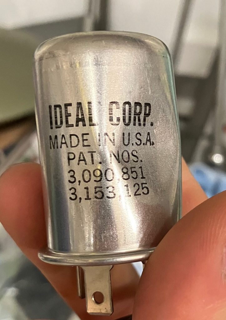
This Ideal Heavy Duty Flasher 537 (12V) is one such oscillator. Although it might be called a flasher relay, it differs from its cousin, the electromagnetic relay.

They come in a metal can and hardly weigh anything – resembling a reed switch or vacuum tube more than a magnetic relay. The can is marked to be used with a 14 amp fuse.
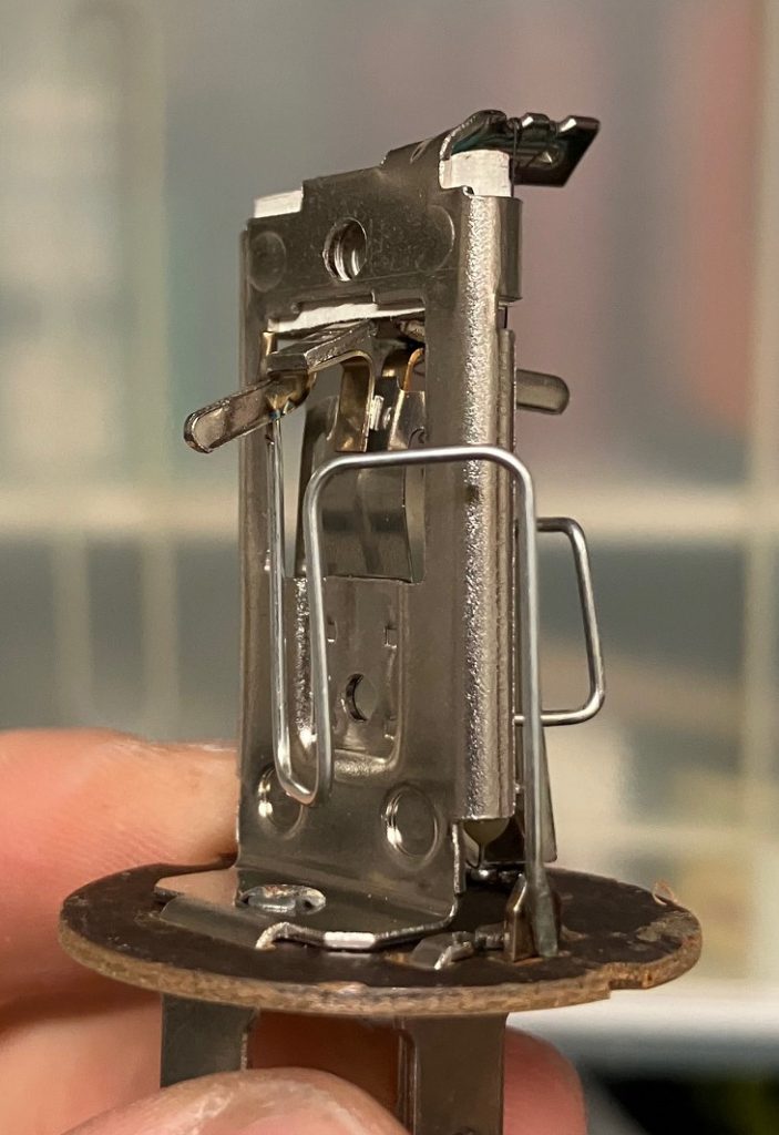
In total, the flasher uses 18-20 components joined by spot-welds, crimps, glue, and rivets.

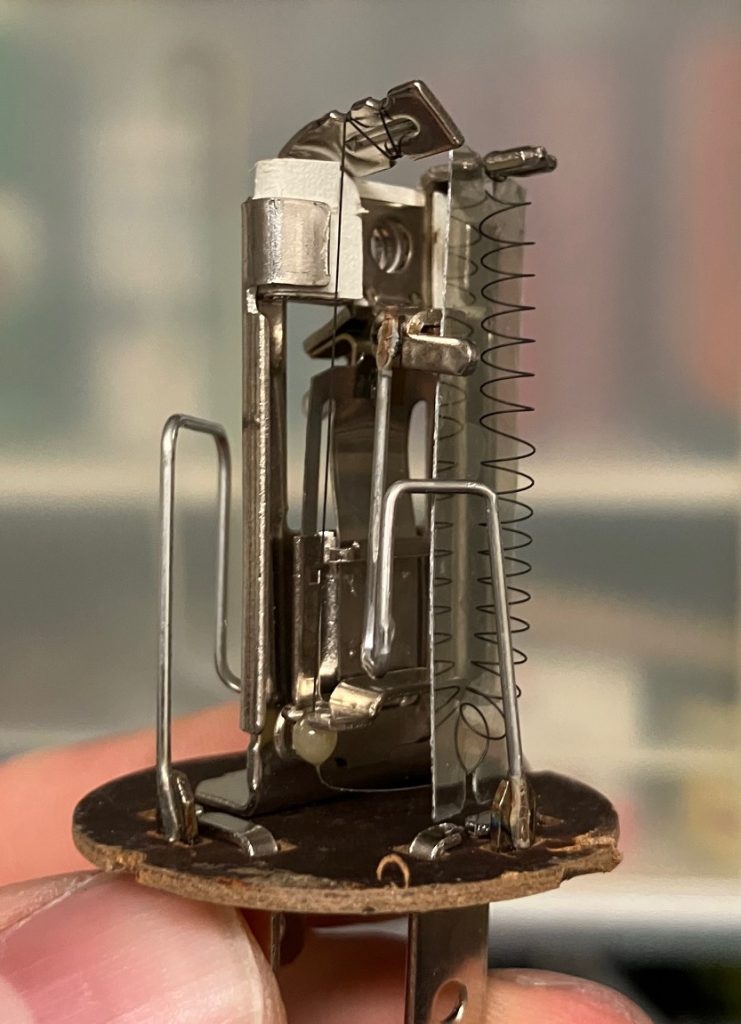
One of the three contacts, X, goes through the base as a single folded sheet, stretching up to the top. The other two contacts (L and P) are routed in free space with metal wire and each contact a different throw on either side of the switch. The throw contacts are silvery metal buttons, embedded in a thin copper sheet, spot-welded to a thicker metal sheet.
Folded paper is crimped between the frame of X and holds the wings of L and P in place at the top of the assembly without shorting them together.

A coiled nichrome wire is welded to a sheet on the L contact near the top. That coil, under little tension, holds an inch-long insulating sheet of mica in place.
At the lower mousebite in the mica sheet, the nichrome takes a turn, loops back upward, and stretches once again all the way to the top where it wraps around the central pillar of X and is spot welded at the top.
Between that turn and the top, the wire is under substantial tension, trapped in place by a glass bead constrained in a metal slot coupled mechanically to the pole X via a lever/spring. The nichrome pulls the pole (X) in tension to contact P when the flasher is de-energized and there’s no voltage between L and X.
In relay terminology, contact P is the normally closed throw, X is the common pole, and L is the normally open throw.
Suppose a voltage is applied across terminal X and terminal L. Current will flow through the nichrome, and it will heat up and lengthen, relaxing the tension on the lever slightly. The lever pole on X bends just enough to lose contact with P, instead contacting L. L and X are now shorted together through the switch, so no current can flow through the nichrome. It cools and eventually contracts; the lever swings back to the P-X position. Current can flow through the nichrome again.
Apply 12 volts to the right pair of terminals and you have an oscillator. Connect a light bulb to the other contact, and now you have a blinker.
The manufacturer, Ideal, used a neat trick in fabrication: the tension can be set at the end, just before encapsulation, by twisting the top arm suspending the nichrome until L just barely makes contact with X.
The extra coiled nichrome is there to keep the resistance high enough that the wire doesn’t burn out at 12V. Quick self-test: would a 24V flasher need more or less nichrome length?
Switching and oscillation are keys to digital logic. In the past, computers have been built from gears, vacuum tubes, electromagnetic relays, and even water. In the future, do you see anyone making use of thermal expansion and contraction to make logical computations?
Thanks for reading.
[Updated to clarify how the switch turns on and off.]
