[2024-07-06: Updated to include simulation results and more scope traces.]
If you own a car, you’ve no doubt encountered this mystery at least once. The tire pressure monitoring system tells you your flat tire is on the driver’s side front, but it’s actually on the passenger side rear.
This is a relatively modern car ownership pain point. The law that mandated tire pressure sensors be installed on every passenger car was only passed in 2007. Before then, only upmarket cars had tire pressure sensors, and they were often based on tire rotation rate. [A tire low on air will have a slightly smaller radius, so it’ll try to spin faster than other tires.] Congress decided that the national rate of accidents due to tire blowouts was too high, so they asked Detroit to do something or face fines.
Such was the birth of Tire Pressure Monitoring Systems, or TPMS.
Today’s typical solution is simple and cheap: exactly what a struggling auto OEM needs to hit the compliance goal. It’s almost an exact copy-paste of the technology found in fobs used for keyless door unlocking – but instead of four variously placed active RF sensors for the fob, there’s just one transceiver for the whole TPMS.
—— | Wireless key fob system | Tire pressure sensor system |
| Easily replaceable battery? | Yup | Not for most people |
| 315 or 433 MHz wireless system-on-chip? | Check | Check |
| Encryption & key exchange? | Check | No need! |
| Atmospheric pressure sensor | Nope | Check |
| Time of flight proximity sensor | Check | Nope |
| Integrated re-learn feature | Check | Nope |
| Battery lifetime | 3 years | 5-10 years |
We return to the mystery of today. Why does a supercomputer with a million times the processing power of the Apollo guidance system – my car – put all the tire pressures in the wrong position? As a driver highly concerned about safety, I’d rather know which tire has an all-too-hip stainless steel straw in its inner sidewall without having to look under each wheel on the shoulder of I-95.
There’s an easy answer: the tire guy decided not to bother reprogramming the tire pressure sensor map because most of his customers don’t bother reading it and would never notice. Few time managers would allocate 10 minutes of a 45 minute job where you’re only making $10-20 to do something 99% of your customers don’t want. Trying to track down a slow leak when the tire map is all mixed up is almost pointless, but most consumers don’t bother – they just drive until the slow leak is a fast leak, and only then get the tire replaced.
I reasoned that having a mismatched TPMS map doesn’t really affect my car’s safety or usability. People drove for more than 50 years without these sensors at all, let alone a perfect map of which tires were at which pressure. If most people only find it useful to get early warning of a super-flat tire, I probably don’t need the precision. I’ll just get over it, right? Ordinarily, this is where the story would have ended. But not in China’s America.

The siren call of cheap eBay listings wailed in the distance.
The consumer in me complains, “it’s only $1, there’s nothing to lose!” The minimalist urges caution; who needs another piece of plastic garbage? But my engineering and economics training brought more questions to the fore: how can these tools possibly be so cheap given the sophistication of what they’re supposed to do? And given how cheap they are, why isn’t there… an iPhone app or software-defined radio widget that does the same thing?
I had to know the answer. Those eBay drop-shippers needed to boost their new accounts’ transaction counts before they resold them. All too happily, we made a market.

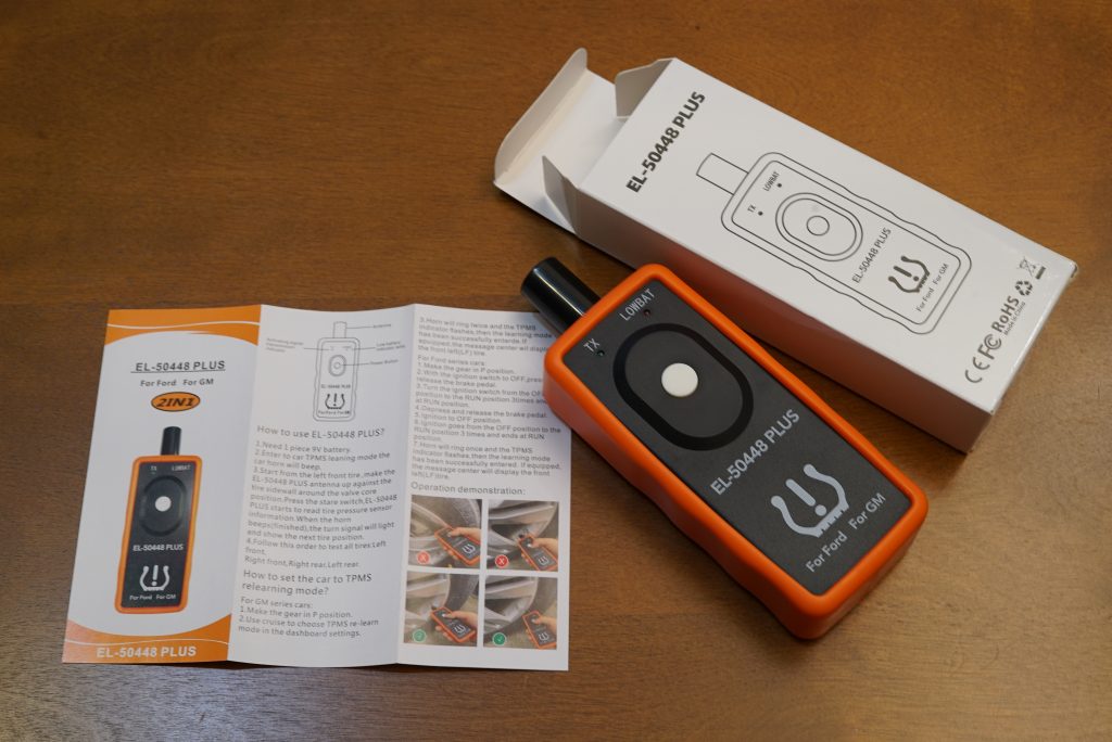
EL50448 Curse of Re-Education
- Go to the tire pressure page on the dash
- Hold the check button on the steering wheel a while time until the relearn menu comes up
- Go to the front left (driver’s side front) tire, point the relearn tool’s antenna directly at the TPMS sensor in the wheel, and press the tool’s button until the car honks.
- Go to the right front (passenger side front) and repeat.
- Go to the rear right (passenger side rear) and repeat.
- Go to the rear left (driver side rear) and repeat.
- Exalt in your newly certified tire pressure display.
Supposedly, I work full-time on things like wireless protocols, sensor networks, power saving modes, enumeration and authentication. [Reminder that the ideas and content here are only my own.] This stuff should be right up my alley. But seeing a nominally complicated re-pairing device selling on eBay for $1 gives me “Temu Microwave Oven for $5” vibes.
After quickly checking that it worked on the car (it did!), I cracked it open.
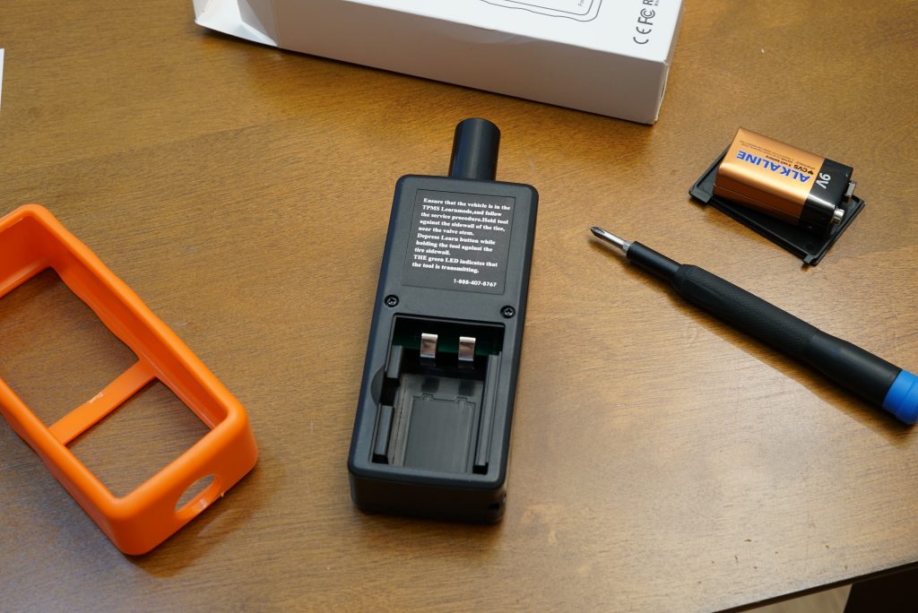
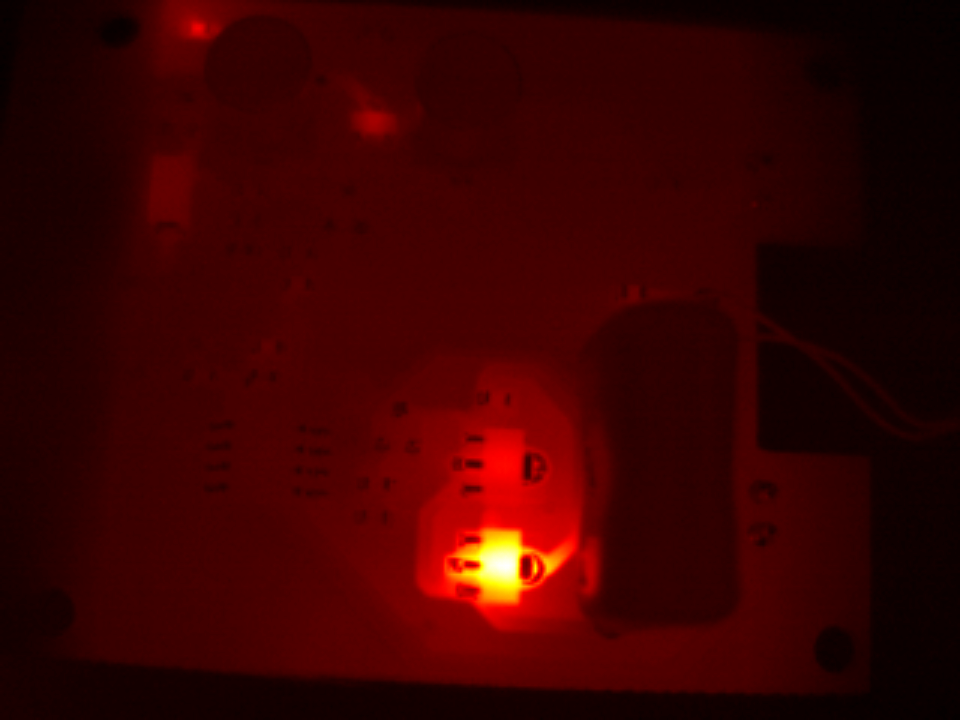
Not a bad design, mechanically speaking. With two plastic clamshell pieces, featuring snap lock positioners, the PCB is held in place and its button pressed solidly into position. A rubber gasket retains the ferrite coil antenna in the plastic antenna housing.
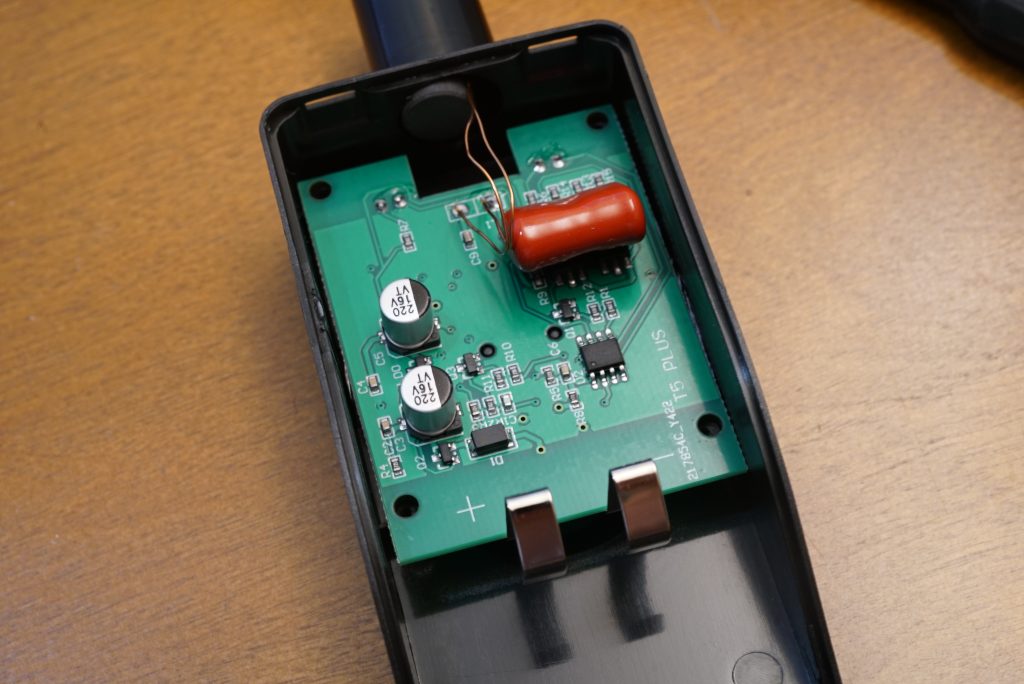
The BOM is impressively small. In order of disassembly, quoted around 100k qty, with some guessing:
- Printed paper manual: $0.04
- Printed paper box: $0.02
- Rubber casing: $0.05
- Injection molded & silkscreened battery compartment cover: $0.03
- Injection molded & silkscreened rear case: $0.08
- Injection molded & silkscreened front case: $0.08
- 2x plastic screws: $0.02
- 30x20mm PCB: $0.10
- Ferrite stick: $0.40
- Copper wire for antenna: $0.05
- Red + green LEDs: $0.06
- NPN J3Y: $0.05
- NPN BLP11: $0.15
- PNP ALP11: $0.07
- Voltage regulator(s): $0.10
- Button: $0.05
- Capacitors: $0.10
- Timer chip: $0.05
- Solder paste: $0.02
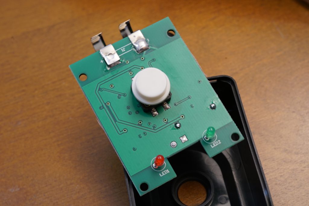
Just over a buck fifty. These sellers are either getting a large quantity discount or are flooding the market to farm eBay seller points. [With free shipping at $1, I would be surprised if they’re not also harvesting names and mailing addresses.]
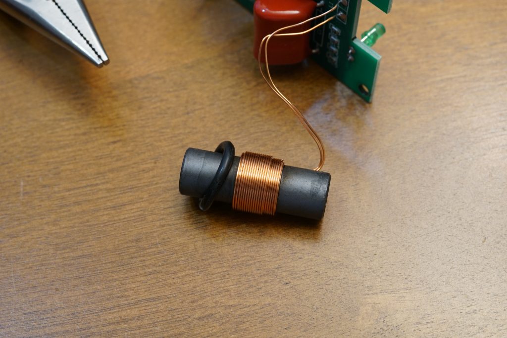
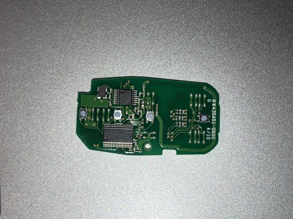
EE hats back on. There’s something strange here. I don’t really see any complicated radio-frequency antenna matching networks or a programmable DFN/BGA packaged system-on-chip. There’s just an 8-SOIC timer chip or microcontroller, some voltage regulation, a few transistors and capacitors, and a ferrite coil antenna.
Here’s a photo of a keyfob PCBA for comparison:
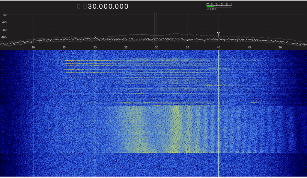
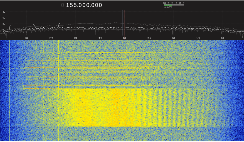
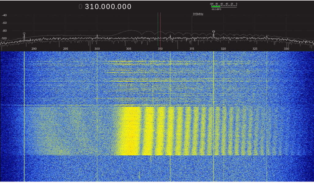
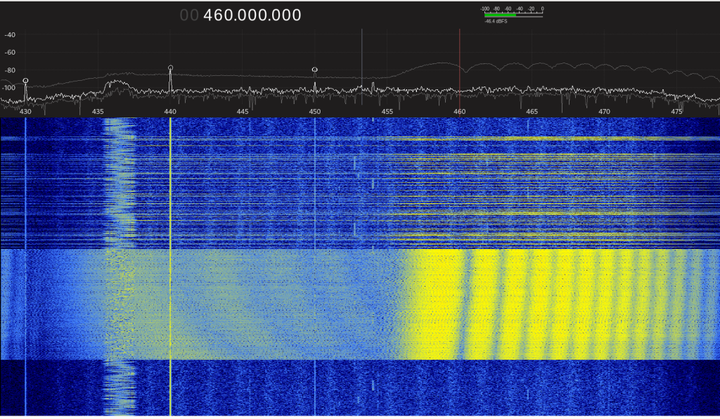
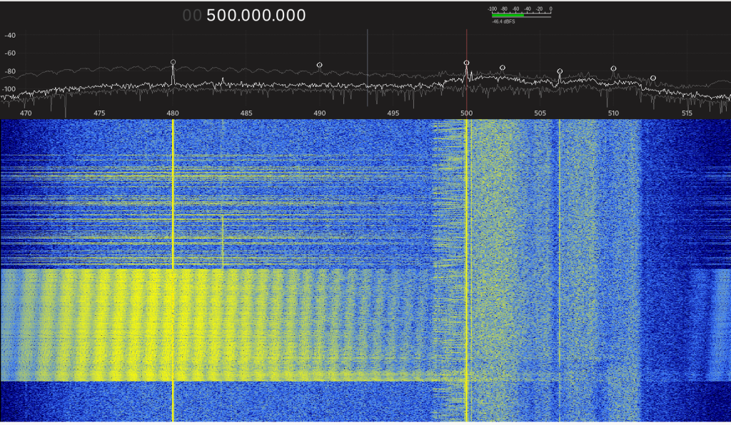
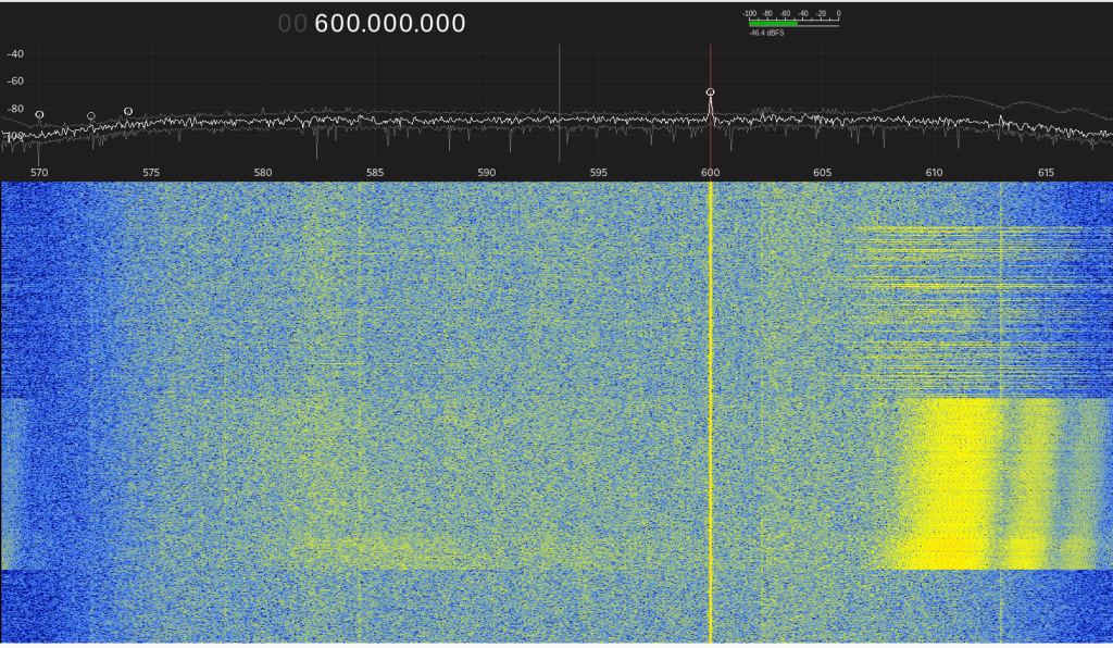
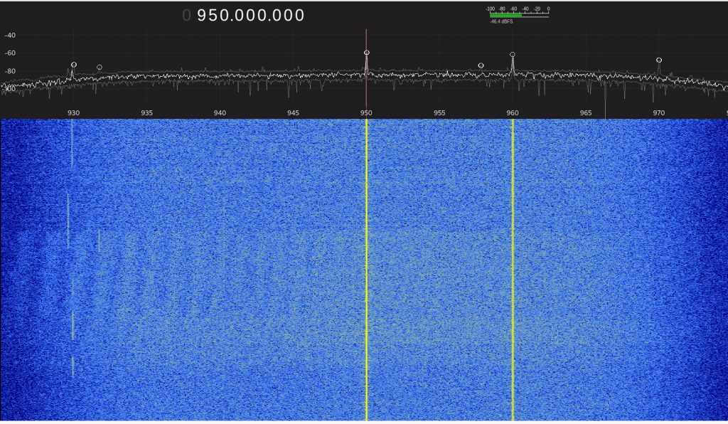
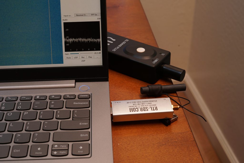
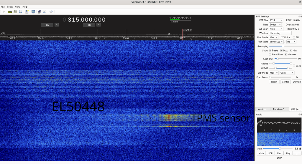
Let’s leave the internal scoping for later and peek at the output spectrum with an RTL-SDR (software defined radio receiver).
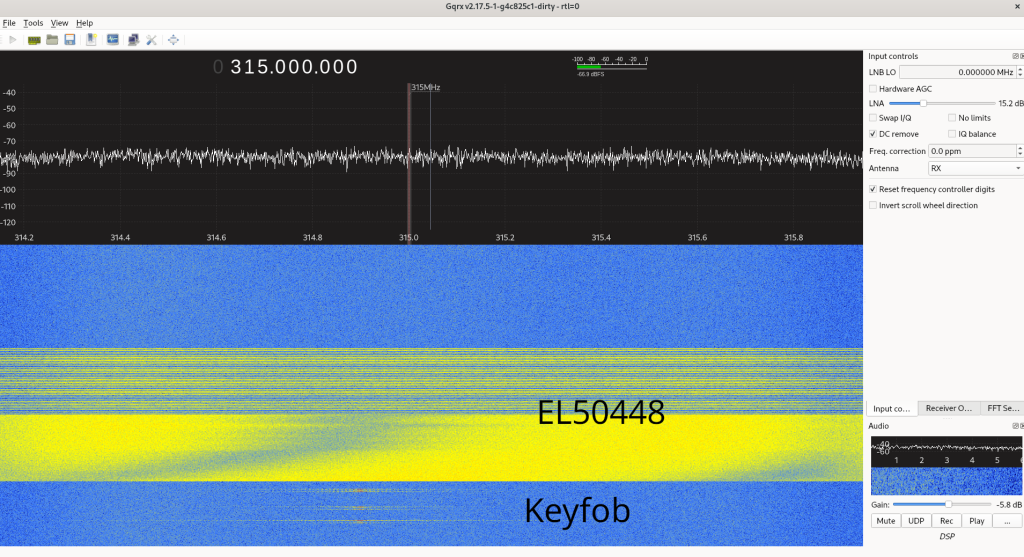
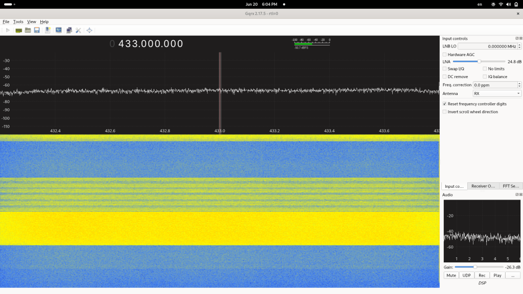
What would you say is happening here? It sure doesn’t look like a meaningful modulated signal to me. I’d say it’s just noise. Solid noise for 5 seconds, then 5 seconds of noise split up into a bunch of equal on/off sections.
But it works!
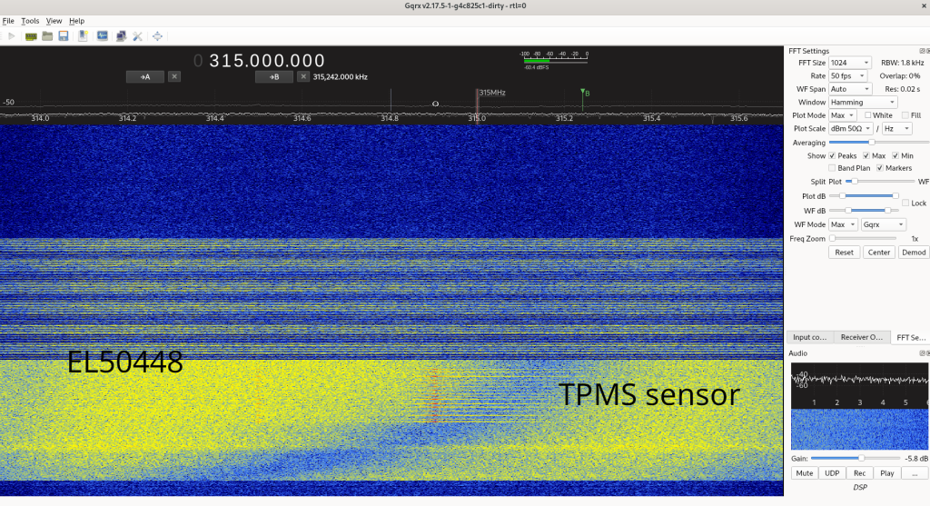
Two other alternatives the internet provides for the TPMS re-learning procedure help with context.
– Option A: With each tire fully inflated, install, deflate, and then re-inflate the tires one at a time starting from the drivers’ side front.
– Option B: With all tires below 40 PSI, pressurize them one at a time to 45 PSI, starting from the driver’s side front, then release them to standard driving pressure.
Each honk during the re-learn procedure signals that the car has registered another sensor’s presence. In embedded jargon, this is referred to as enumeration. In plain English: it identified itself by transmitting the unique numerical signature it sends with each pressure measurement.
There’s no secret code being transmitted. The TPMS sensor simply follows a few simple rules to save power:
1. Unless any other condition is true, it transmits nothing and sits silently.
2. If the pressure measurement crosses 10 PSI towards 0, it enumerates itself.
3. If the pressure measurement crosses 45 PSI towards 50 PSI, it enumerates itself.
4. If the car’s TPMS transceiver requests an update via the 315 MHz band, all sensors in the area enumerate.
5. If the radio front-end detects a signal over a certain power spectral density on the 315 MHz band for a second or two, it enumerates.
#5 seems to be an option that the EL50448 exploits. The original manufacturer of this part refers to it as a “TPMS trigger,” not a re-learn tool.
But how does it really work?
How exactly the tool creates this broad-spectrum noise with so few parts is not clear. From Amazon reviews, the device seems to work reliably only with a brand-new 9V battery. To any EE, that’s a red flag that the design is marginal.
Here was my best guess of the schematic. I couldn’t find exact SPICE models of each part, but on the board Q8 seemed to be BCX56-16, Q7 BCX53-16, and Q1 S8050. L1 is represented as a lumped-element circuit with parasitics R3, C3, and R4. I found SPICE models of each transistor: S8050, BCX53-16, BCX56-16.
The SPICE model I made for this circuit is can be downloaded here; just put those transistor model files in the same directory.

To figure it out in the voltage/time domain, I scoped the board with a DSO5034A. The signal’s source is an unmarked timer IC, U2. It puts out a normal looking 127 kHz square wave around 50% duty cycle with a peak-peak around 3.9V.
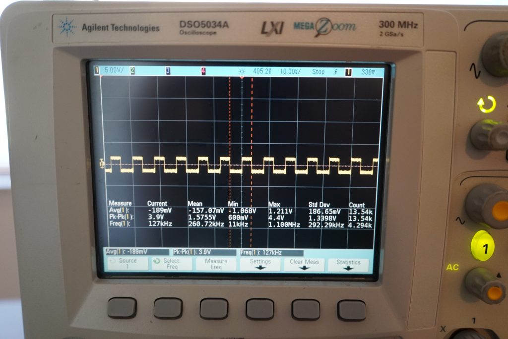
Q1’s base is driven by that square wave through a 1K/10K voltage divider, which reduces its amplitude to 1.16V – just under Q1’s saturation voltage. We can already see some oscillations from further down the signal path:
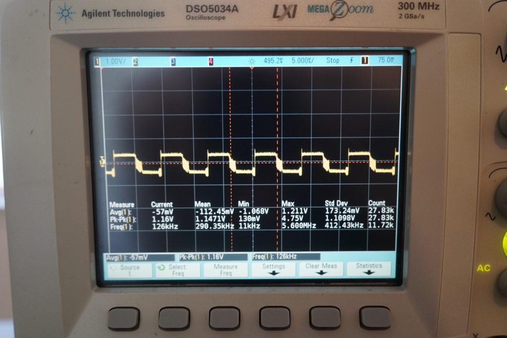
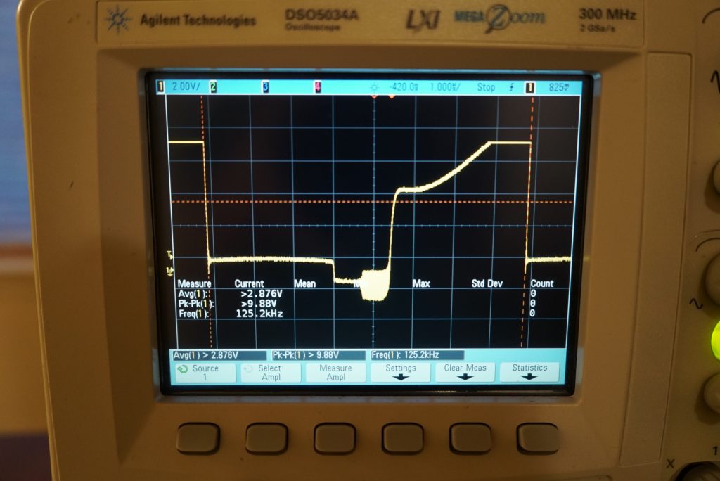
At Q1’s collector, we see the first major distortion of the signal. No longer a square wave, the trace rises rapidly to 6V from 0V, then has a slow exponential rise to the collector bias voltage of 9V, before cycling back to 0V. Oscillations are visible at the rising and falling edges.
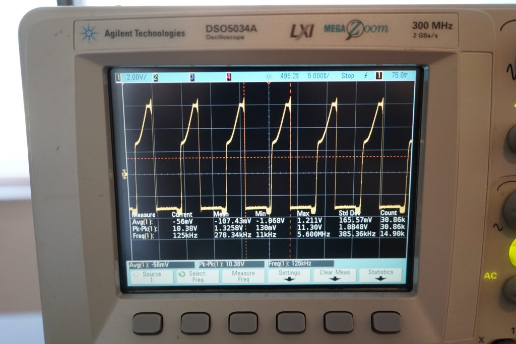
The shared emitter of the coupled NPN (Q8) and PNP (Q7) looks similar: a highly modified 125 kHz square wave with some distortion and ringing. The oscillations before the 9V->0V falling edge are almost entirely gone, while the oscillation before the rising edge has grown from <1V peak-peak to nearly 2V peak-peak.
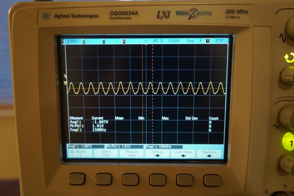
Zooming into the oscillations reveals a non-sinusoidal 159 MHz wave.
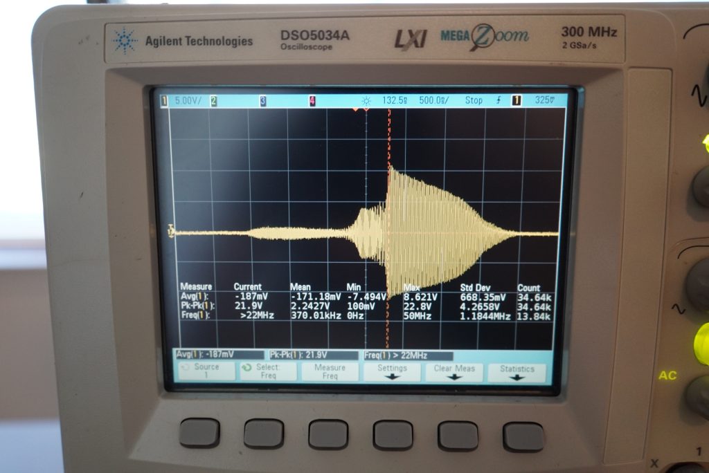
It seems the harmonics from U2’s square wave are amplified, shaped, and filtered into the tank circuit formed by C1/L1. Here’s a scope trace sampled from the last 5 seconds of the wire shared between C14 and the antenna:
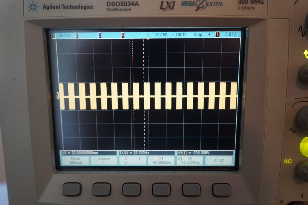
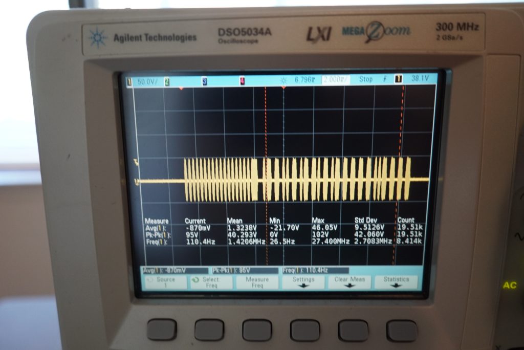
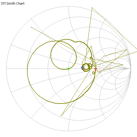
That signal is measured at the high side of the antenna, L1. I took a measurement of L1’s input return loss with a nanoVNA after removing it from the PCB. This antenna has resonant peaks around 100, 280, 350, and 450 MHz. Surely the NanoVNA could give a useful inductance value at those frequencies, right? Nope, it computed -6 nH at 450 MHz.
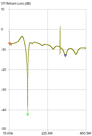
Well, could I just go off the known dimensions of the antenna? It’s a 30x10mm diameter cylinder with around 50 turns of 28 AWG enameled wire near the center. There must be a calculator.
As it happens, modeling ferrite rod coil antennas is not trivial. A guess that seemed to encourage oscillation was 250 nH series L, 0.3 ohms series R, 6K parallel R, and 20 pF parallel C.

At the end of the day, the creators of this device likely also converged on the coil parameters by trial and error. They were given a budget of less than $5 of parts and made it work. LTspice doesn’t have much in the way of ferrite simulation, so this model is as good as we’re going to get.
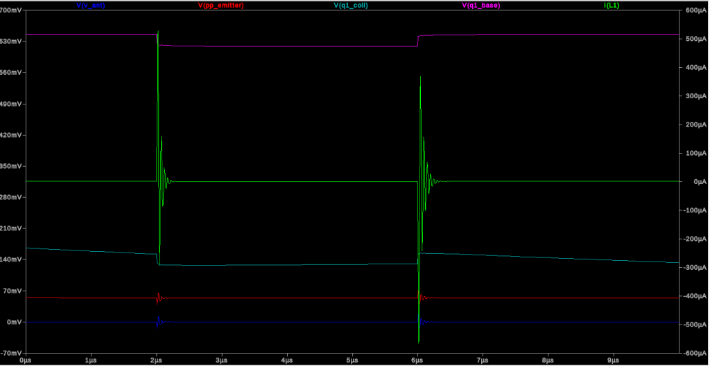
In this simulation, Q1 V_be never reached 1.16V or even varied by more than 500 mV. Nevertheless, the simulation does seem to show some resonant behavior at multiples of 20/50/100 MHz, though the amplitude is super low.
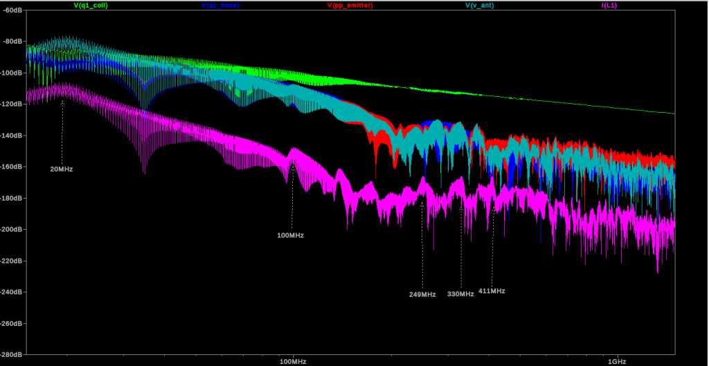
So here’s the breakdown:
- The timer IC U2 generates a 125 kHz signal at 50% duty cycle.
- This is divided down to an amplitude of 1.2V via R1/R12.
- This signal drives the base of NPN transistor Q1.
- Q1’s emitter is grounded; its collector is shorted to Q7 and Q8’s bases and is pulled up to 9V via a 2K resistor.
- Q7 and Q8 form a common push-pull drive circuit; Q7 has its collector grounded and Q8 has its collector directly attached to 9V. Both transistors’ emitters are shorted together to a common output.
- The push-pull output drives a 10 nF 250V film capacitor, a resonant ferrite stick coil antenna, and a 100 nF ceramic capacitor all in series. These likely form a low-Q oscillator with a broad tuning range.
I concluded my reverse engineering effort here mostly because I didn’t want to write a thesis on low-Q ferrite resonator behavior.
Fin
Could you build a GNUradio app to replicate the EL50448’s behavior with a transmit-enabled SDR yourself? Almost certainly. Just create a white noise source at 0 Hz with 20 MHz bandwidth, mix it into a 315 or 433 MHz carrier, and transmit away. Just don’t violate the FCC rules.
The difficult part would be making sure the range is short enough to only enumerate a single TPMS sensor at once. An ordinary dipole won’t fall off with distance as fast as the EL50448’s stick antenna. You might need a ferrite-core coil, but that might not match well with your SDR’s 50 ohm output to the coil. All in all, it’s hard to beat the $1 eBay solution.
Gallery
